

Select the rated capacity of the fire pump or enter the flow you need. See the minimum suction, discharge, relief, test and drain pipe sizes together with the pump room layout.
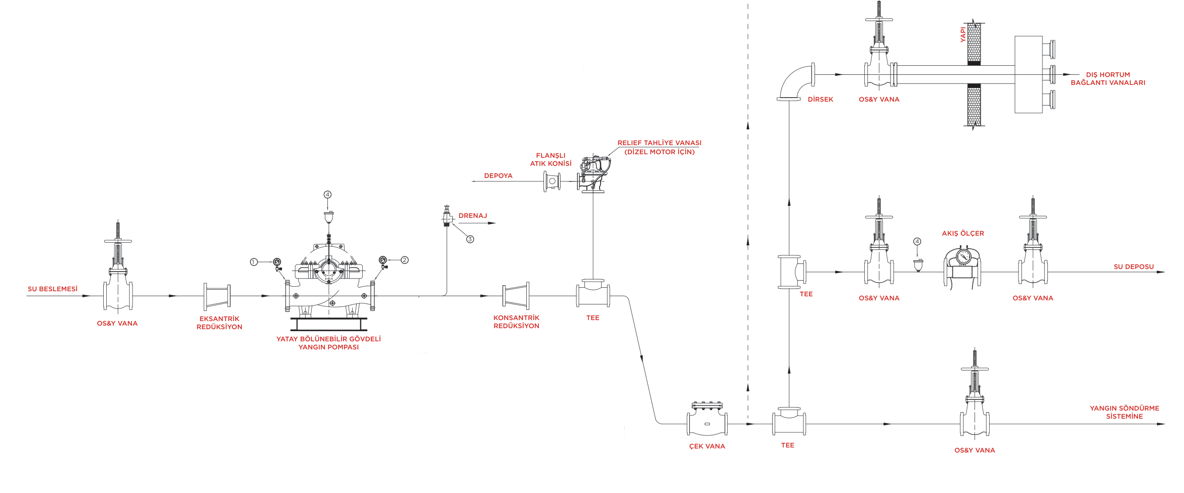
Click the coloured lines, the pump, the valves or the legend above. The selected line is highlighted and the flow direction is animated.
| m³/h | GPM | Suction | Discharge | Relief valve | Relief discharge | Flow meter | Drain |
|---|---|---|---|---|---|---|---|
| 5.7 | 25 | 1″ | 1″ | ¾″ | 1″ | 1¼″ | ¾″ |
| 11.4 | 50 | 1½″ | 1¼″ | 1¼″ | 1½″ | 2″ | ¾″ |
| 22.7 | 100 | 2″ | 2″ | 1½″ | 2″ | 2½″ | ¾″ |
| 34.1 | 150 | 2½″ | 2½″ | 2″ | 2½″ | 3″ | ¾″ |
| 45.4 | 200 | 3″ | 3″ | 2″ | 2½″ | 3″ | ¾″ |
| 56.8 | 250 | 3½″ | 3″ | 2″ | 2½″ | 4″ | ¾″ |
| 68.1 | 300 | 4″ | 4″ | 2½″ | 3½″ | 4″ | ¾″ |
| 91 | 400 | 4″ | 4″ | 3″ | 5″ | 4″ | ¾″ |
| 102 | 450 | 5″ | 5″ | 3″ | 5″ | 4″ | ¾″ |
| 114 | 500 | 5″ | 5″ | 3″ | 5″ | 5″ | ¾″ |
| 170 | 750 | 6″ | 6″ | 4″ | 6″ | 5″ | ¾″ |
| 227 | 1000 | 8″ | 6″ | 4″ | 8″ | 6″ | ¾″ |
| 284 | 1250 | 8″ | 8″ | 6″ | 8″ | 6″ | ¾″ |
| 341 | 1500 | 8″ | 8″ | 6″ | 8″ | 8″ | ¾″ |
| 454 | 2000 | 10″ | 10″ | 6″ | 10″ | 8″ | ¾″ |
| 568 | 2500 | 10″ | 10″ | 6″ | 10″ | 8″ | ¾″ |
| 681 | 3000 | 12″ | 12″ | 8″ | 12″ | 8″ | 1″ |
| 795 | 3500 | 12″ | 12″ | 8″ | 12″ | 10″ | 1″ |
| 908 | 4000 | 14″ | 12″ | 8″ | 14″ | 10″ | 1″ |
| 1,022 | 4500 | 16″ | 14″ | 8″ | 14″ | 10″ | 1″ |
| 1,136 | 5000 | 16″ | 14″ | 8″ | 14″ | 10″ | 1″ |
Pipe sizes around a fire pump are selected according to the rated capacity of the pump. The values in this tool are the minimum sizes required by NFPA 20; pipe length, the number of fittings and pressure losses may require a larger size.
NFPA 20 limits the water velocity in the suction pipe to 4.57 m/s (15 ft/s) when the pump runs at 150% of rated flow. An eccentric reducer with the flat side on top is used at the pump inlet, and no control valve other than a listed OS&Y gate valve may be installed within 15.3 m (50 ft) of the suction flange.
The main line from the pump to the system. A concentric reducer, a check valve and a control valve follow the pump outlet; the test header and the outdoor hose connection branch off this line.
A main relief valve is used when churn pressure plus the maximum suction pressure can exceed the rating of system components, typically with diesel engine drivers. The discharge runs through an open waste cone so that flow is visible, and it is never smaller than the size in the table.
During the annual performance test the pump is measured at 0%, 100% and 150% of rated flow. The metering device must be able to measure at least 175% of rated flow; test water can be returned to the tank.
Releases a small amount of water while the pump runs with no flow so the casing does not overheat: ¾″ for pumps up to 2500 GPM and 1″ for 3000–5000 GPM pumps.
A fire pump must deliver at least 65% of rated pressure at 150% of rated flow, and its shutoff (churn) pressure must not exceed 140% of rated pressure.
Minimum sizes based on NFPA 20: suction pipe 8″ (DN200), discharge pipe 6″ (DN150), relief valve 4″ (DN100), relief discharge 8″ (DN200), flow meter 6″ (DN150) and drain ¾″ (DN20).
Minimum suction 5″ (DN125) and discharge 5″ (DN125). Full list: suction pipe 5″ (DN125), discharge pipe 5″ (DN125), relief valve 3″ (DN80), relief discharge 5″ (DN125), flow meter 5″ (DN125) and drain ¾″ (DN20).
Available pressure on the suction side is limited. A larger pipe lowers velocity and friction loss and reduces the risk of cavitation; that is why NFPA 20 limits suction velocity to 4.57 m/s (15 ft/s) at 150% of rated flow.
No. It may not be needed if churn pressure plus the maximum suction pressure does not exceed the system rating. It is common on diesel driven pumps because overspeed can raise pressure. The decision is based on the project calculation.
¾″ for pumps up to 2500 GPM and 1″ for 3000–5000 GPM pumps.
1 m³/h ≈ 4.403 GPM and 1 GPM ≈ 0.227 m³/h. For example 227 m³/h ≈ 1000 GPM. You can also use the unit converter on this page.
Values are the minimum pipe sizes in the AYSO pump selection table and are based on NFPA 20. Long suction lines, the number of elbows and friction losses may require larger sizes. The final selection must be verified by the project engineer with a hydraulic calculation.